
One of the more common items we sell are timers or relays with a trigger type input. These devices normally have a negative and positive trigger input. They also have positive and negative power connections.
The connection of these devices is normally quite simple, however recently I have been receiving more and more calls about them.
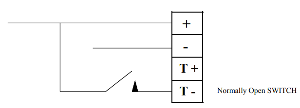
The power connections MUST be used always. These will supply power to the internal circuitry. To trigger the device you must then apply either positive to the positive trigger, or negative to the negative trigger. NOT BOTH. The supplied trigger voltage must also be common with the relevant supply.

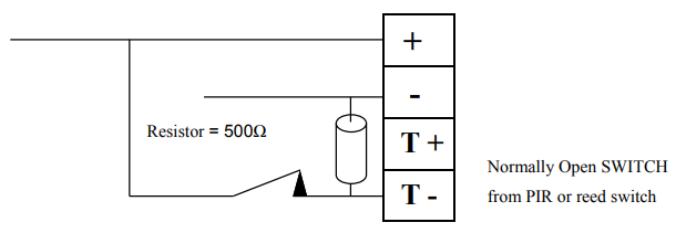
The circuit above is you typical positive trigger circuit for these devices. It utilises a normally open type switch to do the triggering. and it is fairly obvious. What is not so obvious is what to do when you have a normally closed switch to do the triggering, an example of this is a standard PIR.

The operation is reasonably logical, when the normally closed (PIR) contact is closed then the negative trigger line is held to positive, so it does not trigger. When the N/C contact goes open the negative trigger line is pulled to neg via the resistor. The resistor value will vary from device to device.